

Forum Replies Created
-
AuthorPosts
-
zdlAdmin
ParticipantYou are doing great work! Your analysis suggests that the Altura might be working just fine, except for the display! Go ahead and plug a MIDI cable into the device and connect it directly to the MIDI IN of a synth. (Do not try connecting to a computer synth for a first test.) Make sure you plug the sensor cables in correctly, not backwards. You had it correct initially. Point the sensors up toward the ceiling, not down to the table. Set the knobs as described in the Quick Start guide: left, right, 9 o’clock, left, left, noon, noon. This should give you one octave of C Major on the right sensor, and control over modulation or note velocity on the left sensor. The unit will default to transmit on Channel 1 on power up. Go ahead and see if you can control your synth. Do you see any activity on the MIDI light on the slave synth?
When he is able, Altura designer Brach will comment on possible faults in the circuit that could account for the display’s power issue.
Good work! Hey, this is part of the fun!ParticipantInnes, thanks for the video; it is invaluable! Sorry you’re having a little trouble getting your altura fired up, but congratulations on giving it a shot! It is a moderately ambitious project for a first-soldering experience. You seem to have been thorough in your troubleshooting. We are going to look at two things:
1) Are you getting 5V DC distributed around the board? Check the DC voltage to ground at a few places around the board, with the battery in and the power on. Consult the circuit diagram to spot the power pins on the MCU (marked VCC). Also the sensors are easy to measure. Unplug them from the board. One of the end pins should show 5V DC. What do you find?
2) there are three 14-pin ICs that look pretty similar: the multiplexer, shift register and hex buffer, located at U2, U3 and U4 respectively. Examine the nearly-invisible markings on these three components. Are they in fact three different components, with no duplicates? (It happened once.) Are they each in the correct location, in the correct orientation? Any error would account for the observed behavior.
Let us know what you discover.ParticipantThat sounds like a defective pot. We see them about once in every 1200-1500 pots. Our QC process should have caught that, but sometimes the bad behavior is erratic and the unit works fine during testing. If you are willing, I will send you a couple of pots and you can replace the naughty one. Consult the kit assembly instructions to see how we assemble the unit into the cabinet, and follow it in reverse to take it apart. I will need your serial number (on the PCB, starts with ZD) to look up your order.
I’m very sorry for the trouble, but very glad you like/appreciate the design. That makes it all worth coming in to the Lab each morning!Glen
ParticipantDon’t turn it on! It sounds like a ground fault. Look for put pins shorted to each other or to ground.
ParticipantPlasti dip on the outside is strictly optional. It looks neater, and helps hold the copper tape together longer, but is otherwise non essential. Our tests show no measurable difference in sensitivity, but theoretically it costs you something. Inside the mic, between the piezo and the copper tape, it is essential to insulate the disc from the tape. Plasti dip has proven very unreliable for this purpose, so we only recommend a layer of electrical tape.
As for the tin can mic question: Please look at our silly videos promoting the Hula Mic gimmick. This project involved clamping or sticking a complete, shielded mic to all sorts of trash. It is still quite sensitive. The object itself is a much bigger factor in how the mic sounds than the layer of tape on the mic.
In all cases, the sound is heavily influenced by how well the mic is coupled to the vibrating object. Whenever possible, use a little spring clamp and a pad to hold the mic down firmly to the edge of your object. When that’s not possible, we like to use a very small bit of poster tack, mushed up warm and soft, squeezed into a thin sheet, to stick the sensor to the middle of the vibrating object.
I hope this helps?
ParticipantOh yes, it is certainly still happening. We are holding details close to the chest as we continue with our R&D. No release date yet. Sign up for our newsletter to stay abreast of developments…
ParticipantYep, that’s an upside down transformer for sure. These are custom made for us, and apparently one small batch was made with the outer sheet metal enclosure installed the wrong way. You can fix this yourself by bending out the little retainer tabs on the bottom of the transformer, peeling off the sheet metal shell, and flipping it around, installing it again the correct way. If you would rather not deal with this, contact us about an exchange.
ParticipantYes! Yes indeed! MIDI Mod kits are still available though they do not appear on the Quaverato page. It is a small, simple mod that you can order as a kit or with the tiny circuit board already populated. Depending on the date of issue, your pedal may already have a hole in the back panel just itching to accommodate the MIDI jack; otherwise, you will use the supplied template to drill one hole in the chassis.
Just write to us via the Contact Form. Be sure to mention the serial number on your pedal and we’ll fix you up.
ParticipantBesides those two videos, there is a detailed assembly manual available for download from the combo page at http://www.zeppelindesignlabs.com. Winging should not be necessary. But no, we did not shot a separate build video for the combo.
ParticipantHere they are!!
Hmmm… looks like they don’t want to display for me, either… What’s with that?
ParticipantAllow me to interject with a clarification. I believe my partner is referring here here to the toggle y labeled MOM / TOG. This toggle switch toggles the foot switch between Momentary and Toggle modes.
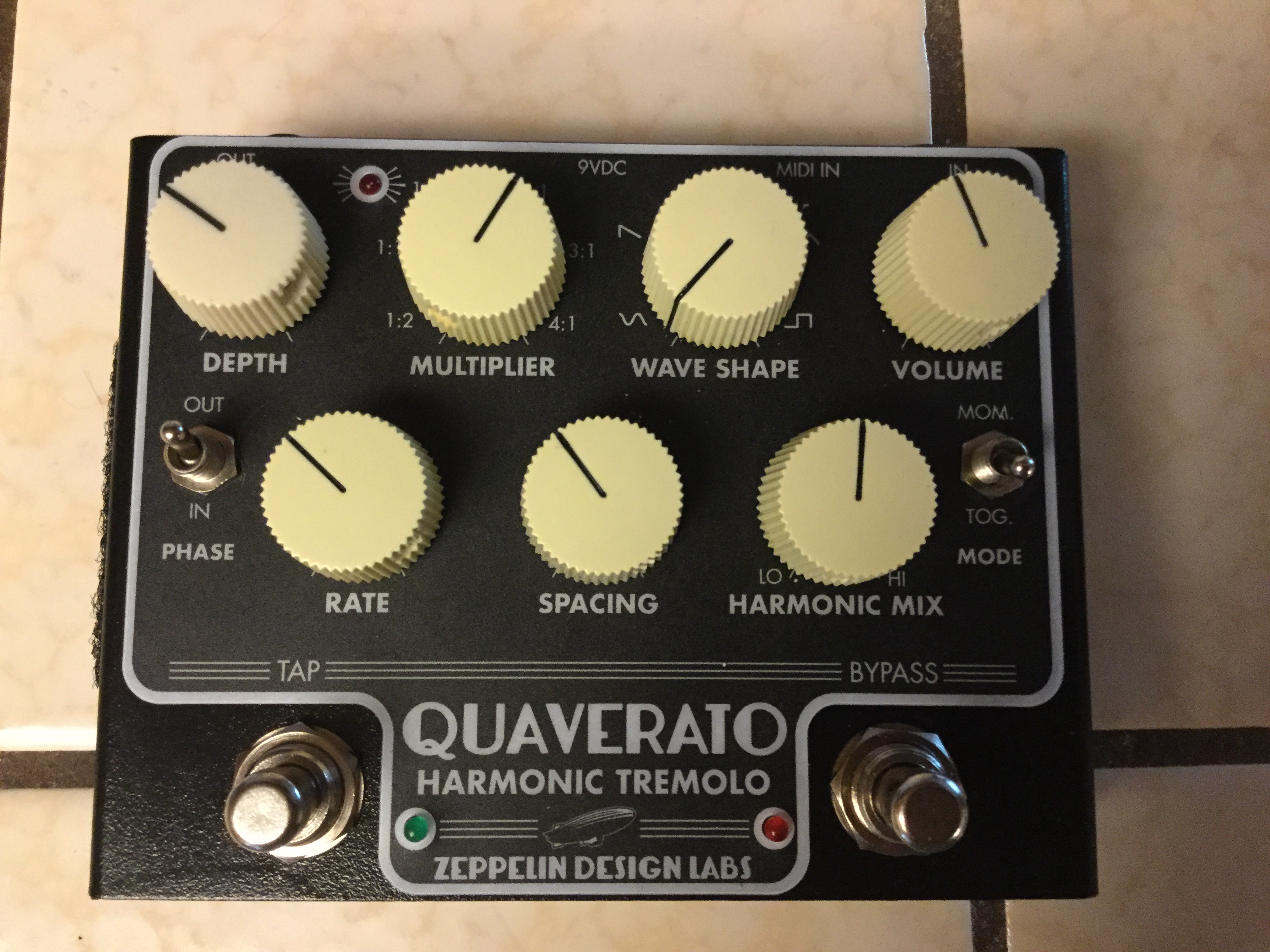
GlenParticipantAnd here it is! Quaverato with Fender brownface style knobs. Nice work, Rusyt!
 Participant
What are you using for a power supply?
ParticipantAnd agian!
 Participant
Rusty, so sorry about the missing hardware!! That’s actually pretty rare. Your nuts and washers are on the way. Thanks for the heads up; we can double check the other kits packed in the same batch.
I’m also sorry it’s tricky to post pictures here, but here is yours, linked from your Facebook post! It looks great!! Good job!

-
AuthorPosts