Shop › Forums › Quaverato Forum › Quaverato FAQ & Support › Depth not how it should be… › Reply To: Depth not how it should be…
 brach
brachThat is very good information. This seems to point to the microcontroller (uC) because the signal getting from the uC to the high side transistor never gets down to 0 volts when the depths is up (unlike the low side). For some reason the pwm seems to never turn all the way off.
The real test is to find out how it behaves when the uC’s signals are switched between the high and low sides. You can try this by lifting one leg of R14 and R13.
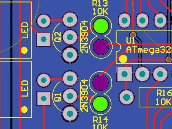
https://zeppelindesignlabs.com/wp-content/uploads/2023/10/zeppelin_design_labs_quaverato_pcb-jpg.webp
In the pcb graphic, unsolder the green dots. Just leave the end of the resistors floating in the air while the other legs are still attached to the board on the purple dot. Find some very thin wire (I use “wire wrap” wire for these types of things) and run a jumper from the floating lead of R13 to the green pad of R14…and run another jumper from the floating lead of R14 to the green pad of R13.
Now turn on the power and test the optocoupler LEDs. If the problem is with the uC then the low led will start behaving like the high led used to, and the high led will start behaving like it’s supposed to.
If the problem is with the transistor (Q1) then the high led will misbehave the way it always has, and the low led will continue behaving correctly.
Let me know what you find out.
-Brach
ps I should have had you measure the resistance of R13 and R14 first to ensure they are really 10k or at least the same resistance value. So do that before you unsolder anything. If they measure different then unsolder one lead and re-measure them.